TH-80-GSM-FAKRA-D
Product Description
This PDF file is to account for the measurement setup and results of BJTEK. The measurement setup includes reflection coefficient, pattern, and gain measurements.
Explanation of Title of TH - 80
T: System code
H: Area code
80: Product type
Product Specification
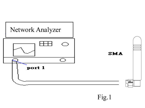
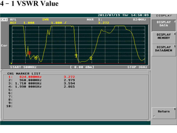
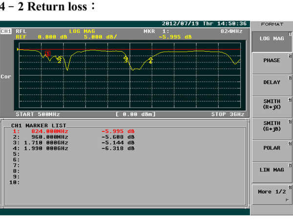
Reflection Coefficient Measurement:
Instrument: Network Analyzer
Setup:
- Calibrate the Network Analyzer by one port calibration using O.S.L calibration kits.
- Connect the antenna under test to the Network Analyzer.
- Measure the S11(reflection coefficient) shown in Fig. 1.
- Generally, the S11 is less than –10dB to ensure the 90% power into antenna and only less than 10% power back to system.
 |
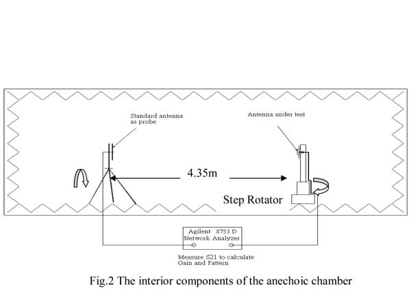
Pattern measurement:
- The anechoic chamber is a far–field measurement system with size of 7m×3.3m×3.3m. The quiet zone region is 30cm x 30cm x 30cm in the center of the rotator.
- The probing antenna is the BBHA 9120 LFA 700MHz ~ 6GHz module (9120D horn antenna), which is placed in the one side of the chamber room. And the antenna under testing (AUT) is placed in the other side of the chamber. The distance between the probing antenna and the AUT is about 4m.
- While we measure the radiation patterns by rotating AUT with 360 degrees and repeat again by replacing the AUT with the standard gain antenna under test, we compare both data and using a formula to obtain the gain of AUT. The standard gain antenna is a gain horn (BBHA 9120 LFA 700MHz~6GHZ).
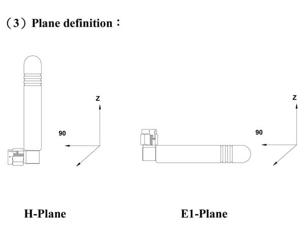
The plane definition for H and E1 planes:
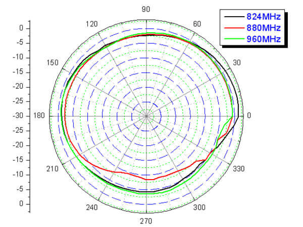
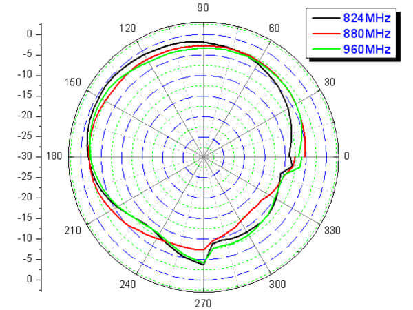
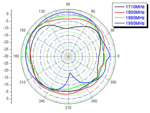
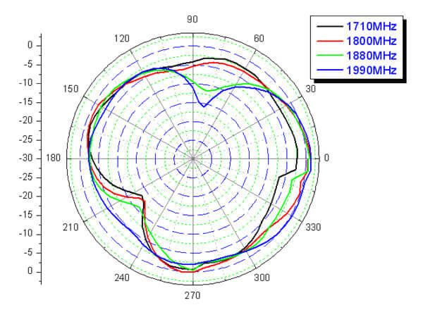
Radiation Patterns:
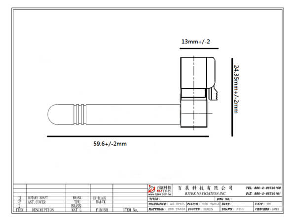
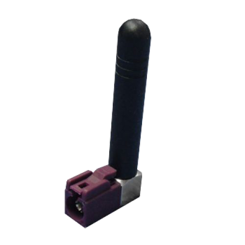
Mechanical Configuration: The appearance of the antenna