MFV-45
Product Description
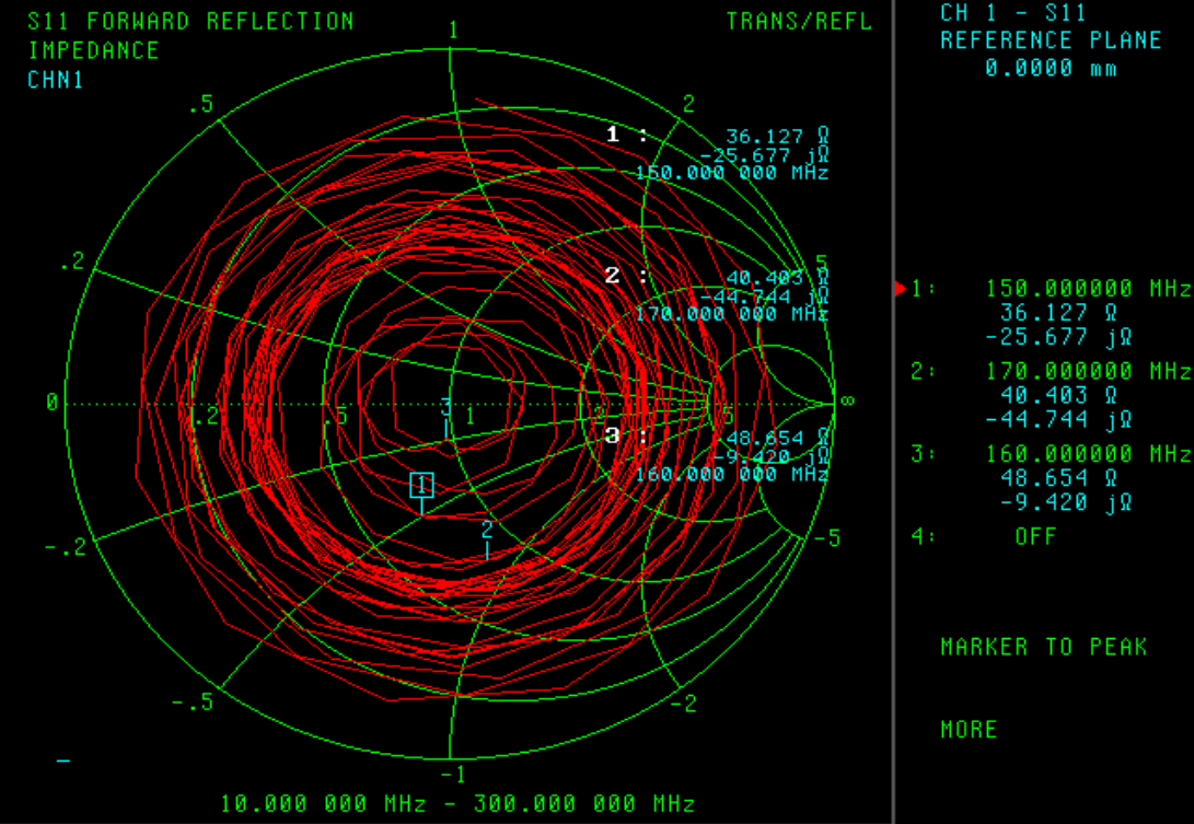
For Automatic Identification System (AIS)
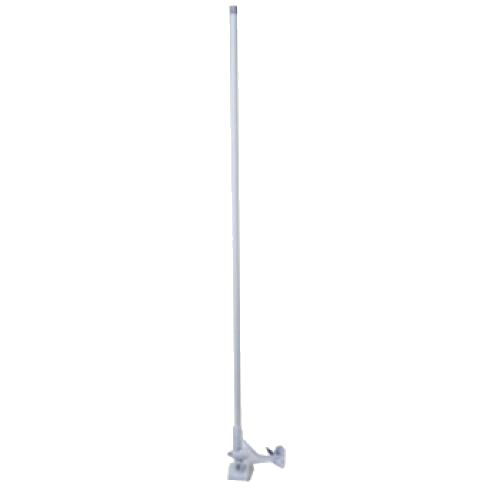
1. APPEARANCE:
2. FREQUENCY:
Product Specification
| Antenna Type | Base Station Antenna |
|---|---|
| Gain | 3 db |
| Fr | 150-170Mhz (160Mhz) |
| Max. Power | 50W |
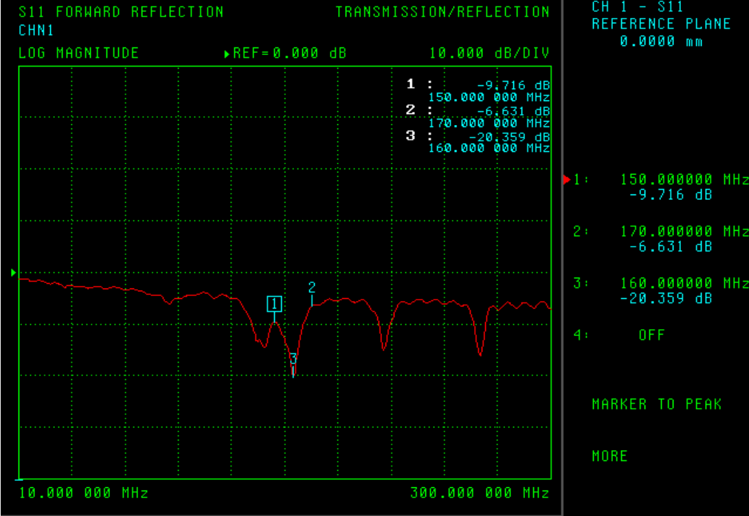
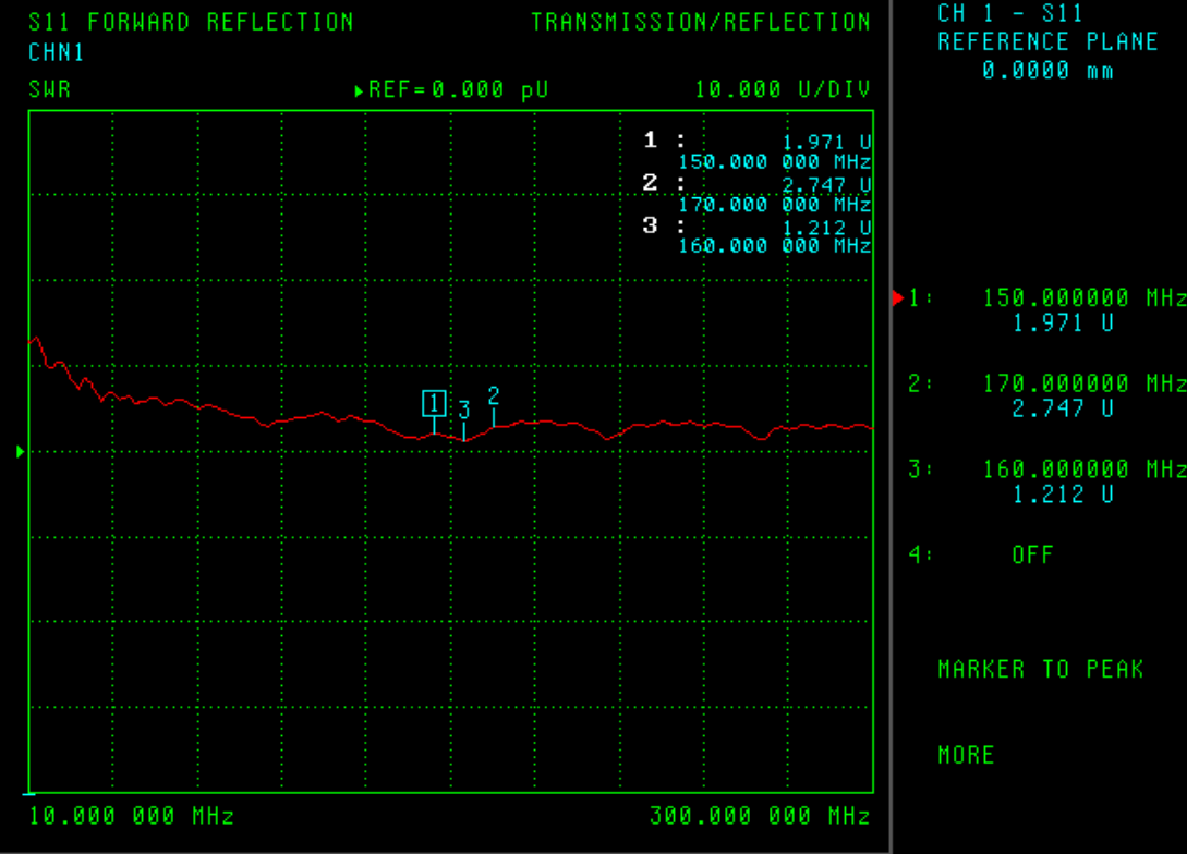
| V.S.W.R | 160Mhz: 1.2:1 |
| Impedence | 50 ohm |
| Connector | BNC , TNC , PL259 , N with RG58 cable 5M or 10M |
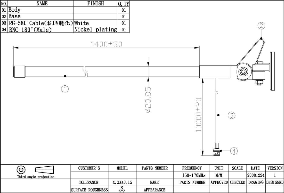
| Dimension | 23.85mm(Dia.) * 1480mm (L) |
| Weight | 1280g (With 10M Cable & FB2 Base mounting) |
| Materials | Fiber |
| Color | White |
Swivel Base Assembly
We recommend assembling the MFV-8 swivel base. Once assembled, you can decide where you want to mount it. The dual swivels allow you to fold over or lay down the antenna just by using the single lever. The second swivel allows for mounting the plate vertically or horizontally or a variety of positions in between.
Refer to the exploded drawing.
A. Put bolt (10) through the flat side of the rotation hub (3) and into the base plate (9) as shown. Piace a washer (8) and nut (7) on the bolt. Hand tighten the nut at this time.
B. Put bolt (1) through the level bar (2) and continue through to top part of rotation hub (3) into the rotation mount (4). Rotation mount (4) has a threaded portion. You must screw bolt (1) into the threaded section of the rotation mount. First screw the bolt all the way in. Then back the bolt out 1-1 3/4 turns.
NOTE: If you fail to back the bolt out 1-1 3/4 turns the fold over lever will not work.
C. Now place washer (5) and nut (6) on bolt (1) and tighten. DO NOT SCREW THE BOLT HEAD IN. KEEP IT STATIONARY AND TIGHTEN THE NUT ONLY. Tighten the assembly by moving the lever counter-clockwise.
D. Mount your base plate in a desired location. Using the bolt (11) assembly Loosen bolt (10) and adjust the unit so that the threaded portion is vertical. Tighten bolt 10.
E. Screw the 8' fiberglass mast onto the swivel base. Route the coaxial cable to your radio. Most people route the cable through the hull. DO NOT CUT OFF ANY EXCESS CABLE. Simply coil it in a 8-12 loop behind the radio.
F. PL259 connectors are very susceptible to corrosion. We strongly recommend use of protectant coatings to prevent corrosion. Corrosion of the connector could case radio fallure. Periodic maintenance may be required.
G. Waterproof the hole for the coaxial cable and your mount with standard marine sealant. The bolts, washers, and nuts used on the MFV-8.are stainless steel. A light coating of protectant will MINIMIZE oxidation in heavy salt spray.
H. To lay your antenna over (fold down), simply turn the lever clockwise. This will release the rotation hub from the mount and should allow you to move the antenna to the horizontal position. If bolt (1) is too loose, your antenna could fall over when the lever is released. If bolt (1) is too tight your antenna may not fold over. To adjust this, hold the bolt in position and loosen nut (6). To adjust for a too loose condition, screw bolt (1) in a 1/4-1/2 turn. Once adjusted, hold bolt 1 in a steady position and tighten nut (6). Reverse this
I. process if bolt 1 is too tight.
J. Your MFV-8 is pretuned for maximum gain and no electrical adjustment should be necessary. Installation is now complete.